I’m using the STM32F2xx DCMI port to receive data from an CMOS image sensor. There aren’t too many Cortex-M3 or M4 parts which have this ability natively; the STM32F2xx is a rare breed. It’s a very nice feature. Along the way I’ve learnt a few things about the DCMI port, some of which are documented, some of which are not.
DCMI Interrupt Only At Frame End
There’s no way to get a DCMI interrupt at the start of a frame. If you need that, route the image sensor’s frame sync pin to a processor GPIO pin, and generate a GPIO interrupt on the rising or falling edge as appropriate.
Data Count Register
One of the things you notice once you start trying to use the DCMI port is that it doesn’t have a simple “data count” register. The way the DCMI port works, is it receives data from an external source and puts it into a small FIFO, which then gets fed to the STM32F2xx DMA controller. For some data types you know exactly how much data you’re going to receive; for other types (particularly jpeg data) you have no idea. But you always need to know how much you have received, and with the DCMI there’s no easy way to know. It’s a surprisingly difficult problem to solve, particularly when you start inserting other things into your image data buffers (like image file headers and the like). When I queried ST tech support about this, they suggested setting things up so an interrupt was generated every time a byte was received. Can you imagine 4 million interrupts a second?
I ended up writing some code to count with the help of the DMA controller. The DMA doesn’t have a “data count up” register either, however it does have a “data count down” register, the NDTR. It gets tricky when you’re using the double-buffer or circular-buffer modes of the DMA controller, because the NDTR register is automatically reloaded by hardware. But with enough puzzling, thinking, head-scratching and experimenting it can be done. Although it’s only accurate to multiples of 4 bytes – see the “zero padding” discussion below.
Ideally I’d like to see ST add a simple “data count” register to the DCMI port, but I’m guessing it probably won’t happen for these parts.
Zero Padding
Talking about JPEG mode, there’s a nasty little “gotcha” in the DCMI port that the documentation does mention in the “JPEG Format” section, but I’ll re-iterate it here. It very much ties in to the lack of a data count register mentioned earlier.
If the amount of data received in a frame is not a multiple of 4 bytes, the DCMI will pad out the end of the frame to a multiple of 4 bytes by inserting zeros. For example, if your frame is 1001 bytes long, you’ll receive from the DCMI port 1004 bytes, consisting of 1001 bytes of “real” data, followed by 3 bytes of zeros.
And therein lies the rub. If you (a) don’t know how many bytes you’re expecting to receive, and (b) don’t know how many bytes were actually received by the DCMI port because it doesn’t have a data count register, then how do you know whether those 3 bytes at the end are padding zeros, or “real data” zeros? In short, you don’t know, there’s no way to tell. You need to consider this, and decide whether or not it might be a problem in your application.
Strangely enough, the DCMI documentation only mentions this zero padding for the JPEG mode, however I would assume (and it’s only an assumption – not confirmed with ST) that this zero padding would occur in the other capture modes as well.
Control Signals Polarity
The documentation is remarkably confusing on this point. If a control signal (eg vsync) is active-high, what DCMI setting is required for that? It’s a bit too difficult to explain, so here’s a repost of a code snippet I posted on the STM32F forum for exactly that question.
// DCMI configuration
// For the image sensor, vsync is "frame sync" and is high when the sensor is transmitting an image.
// hsync is "line sync" and is high when the sensor is transmitting data, low when it's not. It
// will go high and low many times during a frame. The sensor outputs data on the falling edge
// of the clock, hence this processor must clock data in on the rising edge of the clock.
// Note: the F2xx datasheet is incredibly confusing regard V & Hsync polarity. "Polarity_Low" here
// means the DCMI_CR register bit VSPOL/HSPOL is clear, which means the CPU interprets a logic-1 (high)
// sync as meaning "valid data available". Makes no sense I know, but the processor logic is inverted
// from what you'd expect. Tell it zero, it grabs on a 1.

DCMI_InitStructure.DCMI_CaptureMode = DCMI_CaptureMode_Continuous;  // repeatedly process frames
DCMI_InitStructure.DCMI_SynchroMode = DCMI_SynchroMode_Hardware;
DCMI_InitStructure.DCMI_PCKPolarity = DCMI_PCKPolarity_Rising;      // read data on clk rising edge
DCMI_InitStructure.DCMI_VSPolarity = DCMI_VSPolarity_Low;           // data valid on vsync high
DCMI_InitStructure.DCMI_HSPolarity = DCMI_HSPolarity_Low;           // data valid on hsync high
DCMI_InitStructure.DCMI_CaptureRate = DCMI_CaptureRate_All_Frame;
DCMI_InitStructure.DCMI_ExtendedDataMode = DCMI_ExtendedDataMode_8b;
DCMI_Init(&DCMI_InitStructure);
DCMI_JPEGCmd (ENABLE);                            // enable DCMI JPEG mode
Hopefully this will help. As a bonus this code snippet shows how to enable the DCMI JPEG mode.
Unexpected “Frame Skipping” in Continuous Mode
The STM32F2xx DCMI control register DCMI_CR contains a couple of bits called FCRC to select which frames are grabbed. Clearing the bits means “grab all frames”, which is how I use the port.
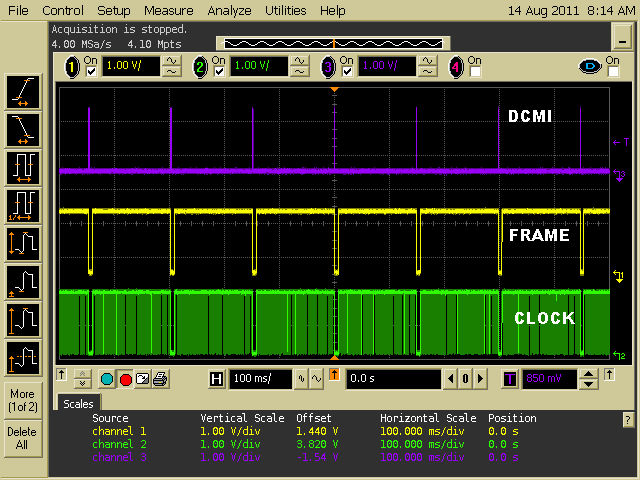
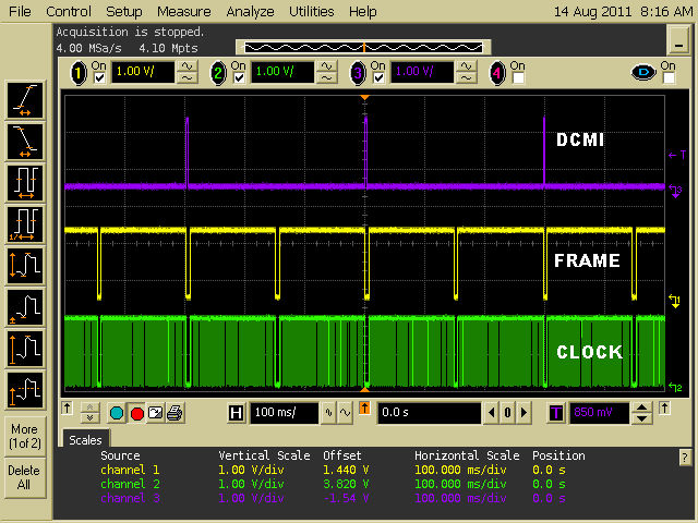
However, I’ve found that despite this, the DCMI can appear to “skip frames”. Take a look at the following two oscilloscope captures. The top trace is a GPIO pin toggled at the start of the DCMI interrupt service routine. The middle trace is the image sensor frame sync pin, and the bottom trace is the image sensor clock pin. As you can plainly see, the first screenshot shows the DCMI triggering on every frame (as expected), where the second screenshot shows the DCMI triggering on every second frame (as you’d certainly not expect).
The difference between these two is a DCMI FIFO overflow. In the case of the first screenshot, the DMA controller is always taking the received data from the DCMI, so the DCMI internal FIFO never overflows. In the second case, the DMA is being turned off halfway through the frame, every second frame. This causes the STM32F2xx DCMI port FIFO to overflow and generate a DCMI error, badly enough to prevent it from generating an “end of frame” interrupt at the end of that frame. However it resets itself at the start of the next frame, which allows it to capture and complete the next frame normally. Then for the subsequent frame the DMA is turned off partway through and the cycle repeats itself.
This was rather unexpected. It seemed like a good idea, turning off the DMA controller once the necessary data was received to save on internal bus bandwidth. However it appears the DCMI peripheral doesn’t like this idea so much, because it doesn’t generate IT_FRAME interrupts properly when this happens. I have not yet had this DCMI behavior confirmed by ST, however it is clear and repeatable on my hardware. I will update this post if I receive any information from ST.
Depending upon the application, losing the IT_FRAME interrupt at the end of a corrupted or overflow frame may, or may not, be a problem. One way to work around this (ahem) “undocumented feature” is to also route the frame sync signal to a GPIO pin, and have the GPIO pin generate an interrupt at the end of each frame. That way you’re guaranteed a GPIO interrupt at the completion of every frame, even if you don’t receive the DCMI IT_FRAME interrupt.
STM32F2xx DCMI Overflow
In my working with the DCMI port I’ve found some other DCMI-overflow related behavior that’s worth mentioning, even though I can’t explain it entirely clearly.
In the second screenshot above, we see IT_FRAME interrupts being missed due to a periodic DCMI overflow, which in turn is caused by software turning off the DCMI’s DMA controller.
The DCMI port can generate an overflow interrupt, called IT_OVR. I tried enabling this interrupt, to see if I would get this interrupt for those frames which are missing the IT_FRAME interrupt. Turning on the IT_OVR interrupt (by setting the OVR_IE bit in the DCMI_IER register) was actually a bit of a disaster – I no longer received any IT_FRAME interrupts at all, and the DCMI port stopped receiving data. It effectively killed the system.
The behavior I saw was this. With both the FRAME and OVR interrupts enabled, initially (after powerup) the DCMI port worked fine, receiving data and passing it to the DMA. After 20 or 30 frames of data I triggered an overflow by momentarily turning off the DMA controller. This resulted in the IT_ OVR interrupt occuring and no IT_FRAME interrupt taking place. I expected this state of affairs to be brief. In fact what happened was the IT_OVR interrupt triggered continuously after that point, and the IT_FRAME never triggered again. Nothing I could dream up would clear the OVR overflow error – it always error’ed again on the next frame, and the next, etc. Even turning off the DCMI port and re-enabling it didn’t cure the problem. It took a reset of the STM32F2xx to have the DCMI port working normally again. This behavior happened even if the OVR interrupt service routine did nothing at all – not even clear the interrupt. Somehow, enabling that OVR interrupt causes the DCMI to behave differently than leaving that interrupt disabled.
I can’t rule out that there was something I was doing wrong, or strange. But for identical incoming DCMI data, if I didn’t enable the OVR interrupt, the DCMI port would recover from an overflow. But if I did enable the OVR interrupt, once an overflow occurred, the DCMI port appeared broken forever. Very strange.
For this reason, obviously, I don’t enable the OVR overflow interrupt – I simply pretend it doesn’t exist.
Other testing I performed, reading the status of the overflow bit in the DCMI port, indicated that the port seems to be tolerant of a certain amount of overflow. Either that or it’s a bit quick to set the flag. I found that even during normal DCMI operation, with the port receiving data and everything apparently going perfectly, the OVR bit could become set. But the DCMI port seemed to ignore it and just continue. I never saw any data corruption or missed data despite the bit being set. Of course forcing a “real” overflow, by momentarily disabling the DMA controller, would also set the OVR flag and in addition would usually cause the IT_FRAME for that particular frame to be skipped. But the subsequent frame would be OK again.
Long story short: don’t enable the overflow interrupt. And if you do, test it (by generating some overflows) very carefully to ensure you don’t end up in some apparently unrecoverable state.
That’s it for the DCMI – the next post will talk about the STM32F2xx SDIO SD Card interface.


32 thoughts on “STM32F2xx Digital Camera Interface (DCMI)”