If you’re designing an electronics product that will ultimately be sold, you need to comply with EMI rules. FCC, CE / CISPR, whatever it might be in your market, these regulations set limits to how much EMI your product can radiate. After all, nobody wants the TV to stop working when your product is switched on.
I’ve recently been playing around, looking at the effect on EMI by changing various parameters of a noisy clock. As we all (should) know, EMI is proportional to current, so reducing signal current (by increasing load impedance, and/or by placing a series resistor in the signal path at the clock driver, and/or by reducing the clock voltage) is the first thing you should do. Shortening the length of the clock trace is a very good idea as well – longer antennas with large loop areas radiate more than short tight antennas.
Beyond that, I noticed that altering the duty cycle of the clock seemed to knock a couple of dB from the EMI level, so I did some simulations in LTspice which appear to confirm this. In LTspice I generated a couple of simple 10 kHz square waves, with 50% duty cycle and 45% duty cycle, and performed an FFT analysis of each. Take a look.
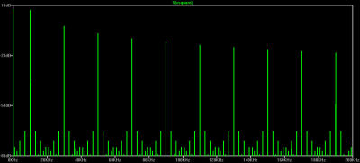
This is the FFT of the 50% duty cycle clock (click on image to enlarge it). The vertical axis is in dB, the horizontal axis is linear. This is similar to how you typically view a spectrum analyzer. Notice the FFT follows the classic F / 3F / 5F / 7F etc harmonics pattern for a square wave.
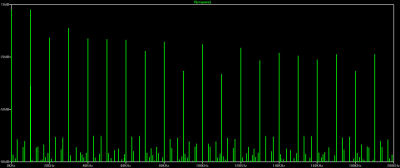
This is the FFT for that same square wave but now with a 45% duty cycle. Click on image to enlarge it.
The scales are the same as before. Notice the big difference – we now have even harmonics as well as odd. So the harmonics are now F / 2F / 3F / 4F / 5F etc. And some of those even harmonics can be strong – you can see the 8th harmonic is noticeably higher than the 7th. Terrible you say?
Not necessarily! Because there’s a deal being made here, which might just be a good deal. In exchange for having even harmonics as well as odd, the harmonics are now lower than they were for the 50% duty cycle case. You can think of energy being taken from the odd harmonics to create the evens. The numbers in the following table are approximate, but they tell the story.
| Frequency | 50% | 45% |
|---|---|---|
| 10 | +7.3 dB | +6.9 dB |
| 20 | -9.1 dB | |
| 30 | -2.6 dB | -3.5 dB |
| 40 | -9.7 dB | |
| 50 | -7 dB | -10.1 dB |
| 60 | -10.4 dB | |
| 70 | -9.8 dB | -16.6 dB |
| 80 | -11.5 dB | |
| 90 | -12.1 dB | -28 dB |
When it comes to passing EMI testing, it’s the peaks that cause you to fail. If your EMI peaks exceed the regulatory threshold, you lose. So anything you can do to reduce those peaks is usually of benefit. That’s the tradeoff that’s being made here. By going with a 45% duty cycle clock, you’re introducing some new harmonics, but you’re reducing the peaks. The amplitude of the fundamental isn’t really being reduced, but for 3F and 5F it certainly is. If you can live with those even harmonics, this can potentially be a very good trade indeed.


