
MQTT is a simple protocol for sharing small packets of data with multiple devices. Although it’s been around since 1999, the last few years it’s been growing in popularity as part of the whole “internet of things” movement. I decided it would be fun to play with it, and based on a posting from home-assistant.io I easily got something running on a quiet Saturday morning.
MQTT is server-based. The idea is some device will publish a message to an MQTT server. For example, “the temperature is 32 degrees celcius”. Then other subscriber devices can register with the server, and will receive that data. Hence conceptually you need three things:
1. a device that’s generating the data (the publisher)
2. the MQTT server
3. a device that registers with the server to receive the data (the subscriber)
I elected to use:
1. An ESP8266 module to generate some test data and publish it to the server.
2. test.mosquitto.org for the MQTT server
3. An Android tablet running the free app “MQTT Dash” to receive and display the data
Hardware Setup
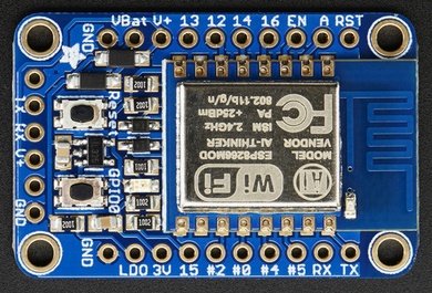
I used an Adafruit HUZZAH ESP8266 Breakout board, because it’s cheap and contains some very useful things on it, like a 3.3V voltage regulator, reset and GPIO0 pushbuttons, etc. Very convenient. They are available from many online vendors (including Adafruit themselves of course). Note the connections on the left of the board picture (labeled TX, RX, V+ and GND) – we’ll be soldering to those pins shortly.
To both power and communicate with the ESP8266 board, I used an FTDI cable. These cables are great because they contain an FTDI USB-to-serial-port chip, plus they also provide USB 5V power. The partnumber of the FTDI cable is: TTL-232R-3V3-WE
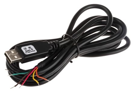
The FTDI cable has six coloured wires coming out the end. Fold back and tape down the brown & green wires so they cannot inadvertently touch anything (including each other); they’re not needed. The remaining 4 wires need to be soldered to the ESP8266 board as follows:
BLACK – to the GND pin
RED – to the V+ pin
ORANGE – to the RX pin
YELLOW – to the TX pin
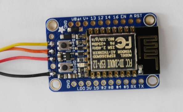
That’s it – 4 wires and you’re all set for both power and communications. Plug it into your PC.
ESP8266 Software Setup
If you haven’t installed Arduino before, follow these instructions for the Arduino and ESP8266 install:
https://github.com/esp8266/Arduino#installing-with-boards-manager
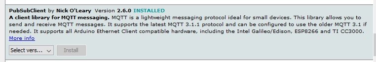
In the Arduino IDE, in the top menus go to “sketch” -> “include library” -> “manage libraries” and install “PubSubClient” by Nick O’Leary.
Now copy&paste the following sketch into a new sketch:
#include <ESP8266WiFi.h>
#include <PubSubClient.h>

#define wifi_ssid "YOUR-WIFI-SSID"
#define wifi_password "YOUR-WIFI-PASSWORD"
#define test_topic "YOUR-NAME/test_topic"

#define mqtt_server "test.mosquitto.org"

WiFiClient espClient;
PubSubClient client(espClient);


void setup() {
  Serial.begin(115200);
  setup_wifi();
  client.setServer(mqtt_server, 1883);
}

void setup_wifi() {
  delay(10);
  // We start by connecting to a WiFi network
  Serial.println();
  Serial.println("Restart");
  Serial.print("Connecting to ");
  Serial.println(wifi_ssid);

  WiFi.begin(wifi_ssid, wifi_password);

  while (WiFi.status() != WL_CONNECTED) {
    delay(500);
    Serial.print(".");
  }

  Serial.println("");
  Serial.println("WiFi connected");
  Serial.println("IP address: ");
  Serial.println(WiFi.localIP());
}

void reconnect() {
  // Loop until we're reconnected
  while (!client.connected()) {
    Serial.print("Attempting MQTT connection...");
    // Attempt to connect
    if (client.connect("ESP8266Client"))
    {
      Serial.println("connected");
    } else {
      Serial.print("failed, rc=");
      Serial.print(client.state());
      Serial.println(" try again in 5 seconds");
      // Wait 5 seconds before retrying
      delay(5000);
    }
  }
}

long lastMsg = 0;
float num = 0.0;

void loop()
{
  if (!client.connected())
  {
     reconnect();
  }
  client.loop();

  long now = millis();
  if (now - lastMsg > 10000)
  {
      lastMsg = now;

      num = num + 1.0;
      Serial.print("New test data: ");
      Serial.println(String(num).c_str());
      client.publish(test_topic, String(num).c_str(), false);
  }
}
Edit the three lines: wifi_ssid, wifi_password and test_topic to suit you.
#define wifi_ssid "YOUR-WIFI-SSID"
#define wifi_password "YOUR-WIFI-PASSWORD"
#define test_topic "YOUR-NAME/test_topic"
Then build (press the “tick” button”).
To download to the ESP8266, press and hold the GPIO0 button, While pressing it, tap the reset button, then release the GPIO0 button. The red LED should now be dimly lit, which indicates it’s ready to receive a download.
Press the Arduino IDE download button (the right pointing arrow). If it doesn’t work, in the menus go to “Tools” -> “Port:” and change the selected COM port, then try again.
As you can see from looking at the code, every 10 seconds this sends an incrementing number as a string.
Go to “Tools” -> “Serial Monitor”, change the baud rate to 115200, and you should see messages appearing. Press the reset button on the ESP8266 board, so you can watch everything start again from scratch.
Android Setup
To receive the MQTT messages, install “MQTT Dash” on your Android tablet or phone:
https://play.google.com/store/apps/details?id=net.routix.mqttdash
You’ll be faced with an almost empty screen. Press the “+” button to add the mosquitto server. Give it a name “eg “mosquitto” and an address: test.mosquitto.org
Have the user name, user password, and Client ID all be blank. Save (top-right icon).
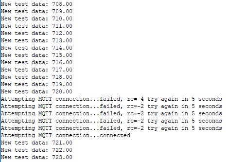
Tap on your new “mosquitto” line item and it should connect. If not, go back & check your server name spelling. Now press the “+” button to add a data item. Select a type of “Text”. Give it a name (eg “test data”) and for the Topic give it whatever you put in the “test_topic” Arduino sketch field (eg: “YOUR-NAME/test_topic”). Hit save. Wait a few seconds and you should start seeing your number string appear. That’s as simple as it is. This sketch can be easily edited to send numbers instead of strings (in which case MQTT Dash can draw pretty pictures of it), you can hook the ESP8266 board to various sensors and have it transmit the data, etc. Just be aware test.mosquitto.org is a free and open test server, so don’t send sensitive information over it, and do expect it to be unavailable at times (it’s busy and it’s a test machine). For “real” applications you should use a commercial MQTT server plus security (client certificates). Here’s a sample of the serial port output; you can see how the test.mosquitto.org server sometimes doesn’t accept the connection. Don’t rely on it for any real applications. But it sure is fantastic for tests.
Useful links:
Adafruit ESP8266 board pinouts:
https://learn.adafruit.com/adafruit-huzzah-esp8266-breakout/pinouts
FTDI cable pinouts:
http://www.ftdichip.com/Support/Documents/DataSheets/Cables/DS_TTL-232R_CABLES.pdf
ESP8266 Arduino Source Code MQTT example and instructions, from home-assistant.io:
https://www.home-assistant.io/blog/2015/10/11/measure-temperature-with-esp8266-and-report-to-mqtt/
The API for the Arduino MQTT package:
https://pubsubclient.knolleary.net/api.html
MQTT Dash Android Application:
https://play.google.com/store/apps/details?id=net.routix.mqttdash
The mosquitto server: